Use cases
On this page, some of the possibilities are explained step by step. Because of the flexibility of our devices, the possibilities are endless. If your scenario is not on this page or you have questions on how your situation can be tackled using MaNima devices, contact us or use the chat function in the bottom right corner.
Jump to a section:
Synchronized Playback
Imagine a scenario where the Magnus LED driver falls short on ports due to the simultaneous control of an extensive array of LEDs. In this situation, the synchronized playback feature comes to the rescue, allowing seamless coordination and control, ensuring a harmonious and vibrant lighting display across all connected LEDs. This function also works when recording.
Follow the step by step walktrough to setup this feature:
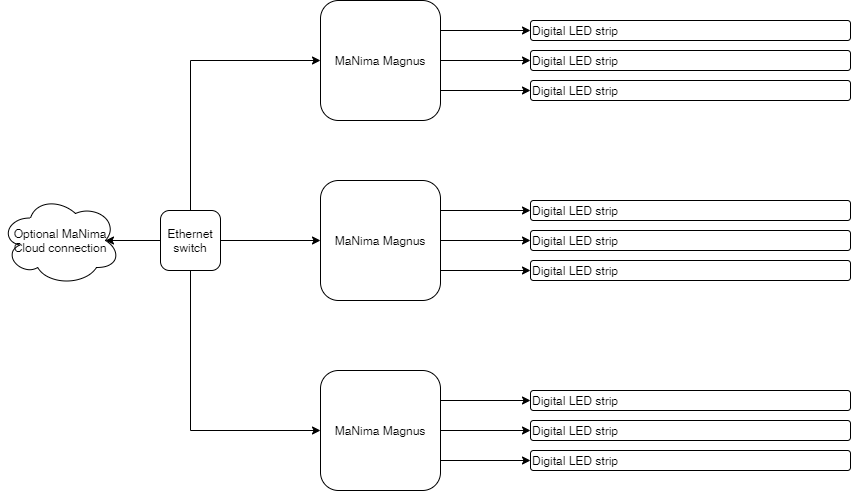
Connect each Magnus to the same network
Make sure all Magnus devices are in the same network. This can be checked by using the scanner function from the GUI. All Magnusses are discovered and must be within the same IP range.
Make sure each Magnus is in the same group
Using the GUI, select one Magnus and go to the group tab. Find each device in the list and change the group number to 1 (anything but 0).
Note: When changing the group of the selected Magnus the list of devices will change to only devices within the same group
Start generating LED data using your favorite software
In this example we use Lightjams LED mapper (LJLM) to generate ArtNet data.
Open LJLM, create a stage and add the LED strips and/or pixels to the patch. Try to lay-out the LEDs as they are in the real-world. This way the effects are displayed perfectly!
Select the right amount of channels (RGB or RGBW) and the right color order! However, the Magnus can change the color order live if something is wrong.
Go to the live tab and select an effect. There should be some light coming from the system now!
Note: LJLM starts counting at universe 0. The Magnus configurator starts counting at 1. This means when adding universe 1 in the configurator, it means using universe 0 in LJLM!
Make sure every Magnus is outputting data
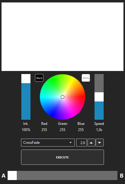
To make sure all colors are in the right order, select or create an effect of a static white color. Using the color filter wheel in the center of the screen, move the filter to the red part and make sure all LEDs are red. Do the same for green and blue, and white if the system consists of RGBW LEDs.
Record a scene
Using the GUI, select a Magnus. Go to the scenes tab and there at the bottom there is the recording tool. Make sure the system is playing the desired effect.
Fill in a name (make sure it does not exceeds 12 characters) and press record. Since the Magnus is added to a group other than 0, it will automatically start recording on all the devices that are in the same group.
Next to the record button it shows how many other devices are recording. Make sure this is equal to the amount of devices that are in the group (without the one currently selected!).
When the effect is recorded to your satisfaction, press stop recording. If no error pops up, every device now has got a scene of the given name.
Playback time
To playback in a synchronized fashion, select the “Synchronized playback” button in the GUI on the Scenes tab. Make sure the player is not playing when setting this flag. After the synchronized playback was set, select the recording that was created earlier. Press play and voila, all Magnusses are outputting what was previously recorded!
Pollux as Monitor
Consider a scenario where you have a digital LED system, and you wish to monitor temperatures for added control and safety. In this case, the Pollux can be deployed as an extension, dedicated to monitoring temperatures. By seamlessly integrating with the Magnus LED drivers, the Pollux ensures comprehensive temperature monitoring, allowing dynamic adjustments and dimming of the Magnuses to maintain optimal performance and enhance the longevity of the entire LED system.
Follow the step by step walktrough to setup this feature:
Connect each Magnus and Pollux to the same network
Make sure all devices are in the same network. This can be checked by using the scanner function from the GUI. All devices are discovered and must be within the same IP range.
Use the GUI to connect the extension
On the scanner tab, select one of the Magnusses that should response to the temperature. Press the 3 dots on the right in the scanner. Select “Connect Extension”.
Select the Pollux in the list, which is based on MAC address. If the Pollux is only used to monitor, select “Monitor” on the next page. Press Finish to exit the wizard.
Note: the “Full” option can be used only once per Pollux. In this way, the Magnus will send lightning data to the Pollux and is not used in this walktrough.
Setup the extension channels
To setup which channels are used by the Magnus, select it in the Scanner tab of the GUI. Go to the Extensions tab and select the Pollux that was previously connected. On the bottom of the screen, press “Add channel”. A channel is now added.
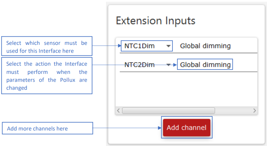
For this walktrough, select Global dimming as effect. Note that the amount of dimming for each NTC is configured in the Pollux, not in the Magnus.
Test if the extension is properly working
There are two ways to test the system:
Heating the NTC
Use a lighter or other heatsource to heat the NTC connected to the Pollux. Make sure not to overheat the NTC and damage it! Check if the Magnus’s output is being dimmed, and that it comes back when the NTC cools down.
Lowering the temperature limits
By lowering the temperature limits in the Pollux, it starts dimming earlier than in normal use. To do this, select the Pollux in the GUI and select the NTC/LDR tab. Change the settings of the NTC that must be tested. This is explained in detail in the user manual.
DMX Control Pollux
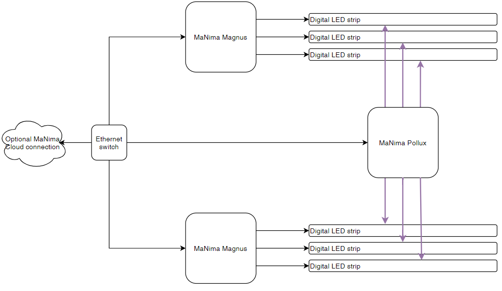
Consider a scenario where you aim to control your Pollux system with DMX, utilizing a Magnus for this purpose. In this setup, the Magnus plays a unique role by transmitting pre-recorded data via ArtNet, while DMX is employed to initiate and conclude specific scenes. This innovative integration not only leverages the Magnus’s ability to transmit stored data but also enables precise control over scene transitions in the Pollux system, providing a versatile and dynamic solution for your high power lighting control needs.
Follow the step by step walktrough to setup this feature:
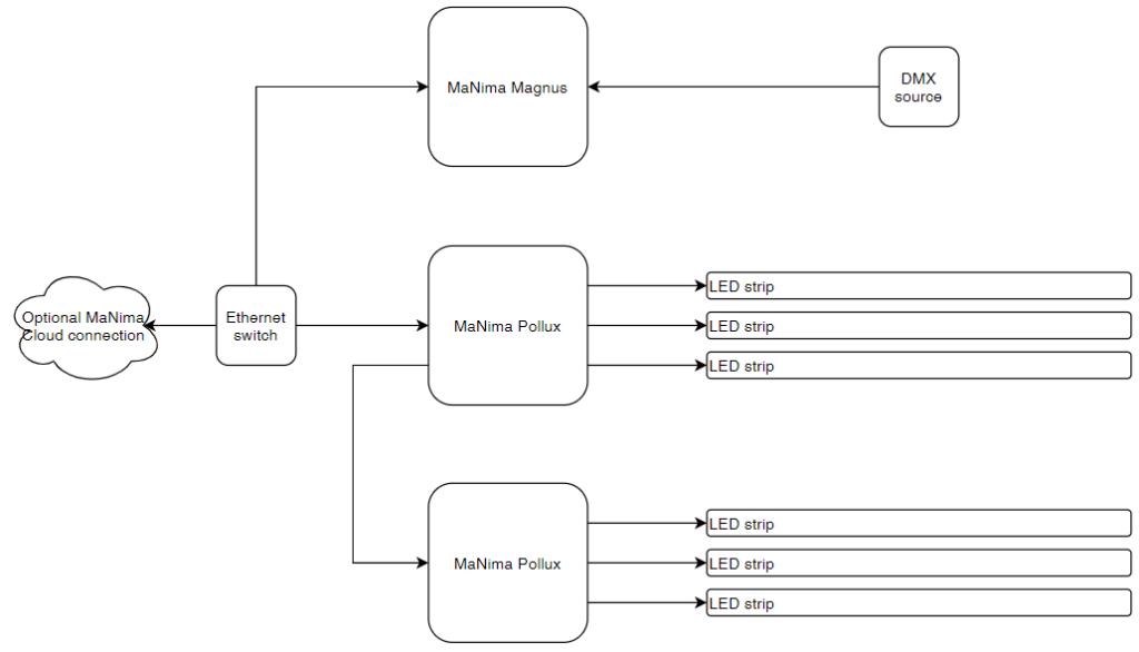
Note that the Pollux devices network connection are daisy-chained. This is optionally and is not a requirement.
Connect each Magnus and Pollux to the same network
Make sure all devices are in the same network. This can be checked by using the scanner function from the GUI. All devices are discovered and must be within the same IP range.
Use the GUI to connect the extension
To connect the Magnus to a Pollux device, follow these steps:
- On the scanner tab, tap the Magnus.
- Tap the three dots on the right side of the scanner.
- Tap “Connect Extension”.
- Choose a Pollux device from the list based on its MAC address.
- To enable the Magnus to send lightning data to the Pollux, tap “Full”.
- Tap Finish to close the wizard.
- Repeat this for every Pollux device that should receive data.
Note: the “Full” option can be used only once per Pollux. In this way, the Magnus will send lightning data to the Pollux and is not used in this walktrough.
Configure the Pollux output
For each Pollux, setup the output universe and channel settings. This ensures the Magnus will send the right data.
- On the scanner tab, tap the Pollux
- Tap the Output tab
- For every output, setup the universe and channel number
Start generating LED data using your favorite software
In this example we use Lightjams LED mapper (LJLM) to generate ArtNet data.
Open LJLM, create a stage and add the LED strips and/or pixels to the patch. Try to lay-out the LEDs as they are in the real-world. This way the effects are displayed perfectly!
Select the right amount of channels (RGB or RGBW) and the right color order! However, the Magnus can change the color order live if something is wrong.
Go to the live tab and select an effect. There should be some light coming from the system now!
Note: LJLM starts counting at universe 0. The Magnus configurator starts counting at 1. This means when adding universe 1 in the configurator, it means using universe 0 in LJLM!
Make sure every device is outputting data
To make sure all colors are in the right order, select or create an effect of a static white color. Using the color filter wheel in the center of the screen, move the filter to the red part and make sure all LEDs are red. Do the same for green and blue, and white if the system consists of RGBW LEDs.
Record a scene
Using the GUI, select the Magnus. Go to the scenes tab and there at the bottom there is the recording tool. Make sure the system is playing the desired effect.
Fill in a name (make sure it does not exceeds 12 characters) and press record. Let it record for how long your desired effect is.
When the effect is recorded to your satisfaction, press stop recording.
Playback time
To playback, select the Magnus and go to the Scenes tab. Select the file that was previously recorded and press play.
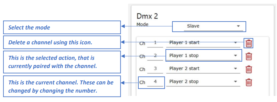
Setting up DMX triggers
To have the Magnus start a scene based on a DMX channel value, configure the DMX settings in the Magnus.
- Select the Magnus in the Scanner and tap the DMX tab
- Set the right DMX port to Slave, as it’s receiving data
- Use the “Add channel” button to add channels to listen to
- Configure the channel value and the effect is should apply
- To have different channels start different effects, pre-load the scenes using the Scenes tab and selecting the other players (player 1 to 5 tab)